In this section, we describe the main A/D conversion processes.
1.1. Double-Integral Type A/D converter
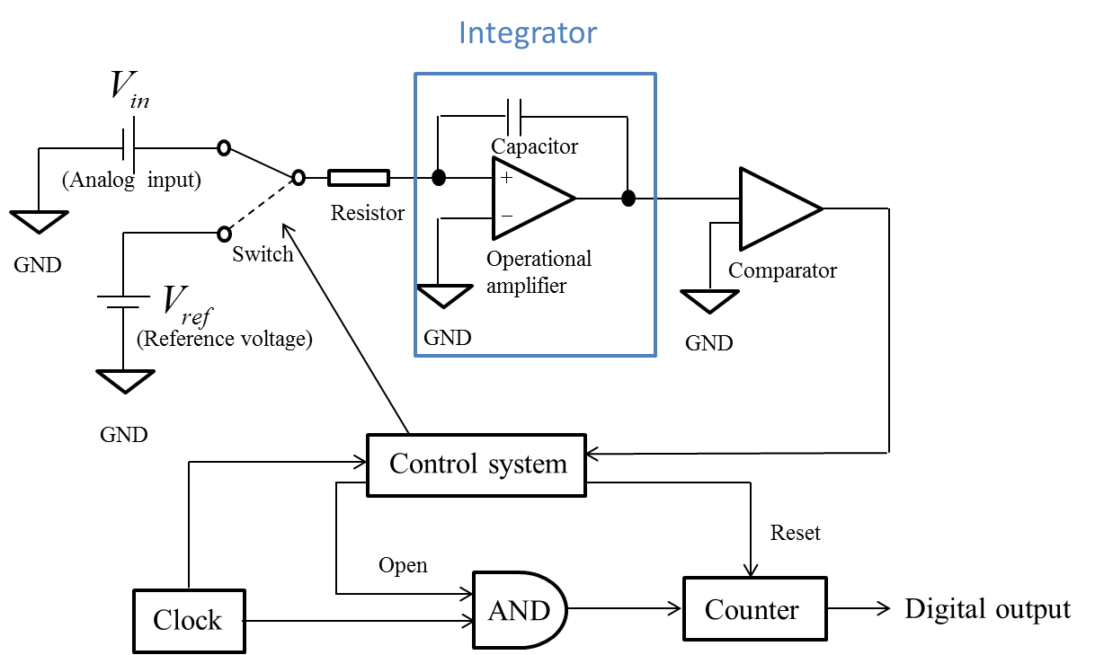
A double-integral A/D converter converts analog information into digital data by counting clock signals (Figure 1). The A/D conversion is performed according to the following steps.
Step 1:
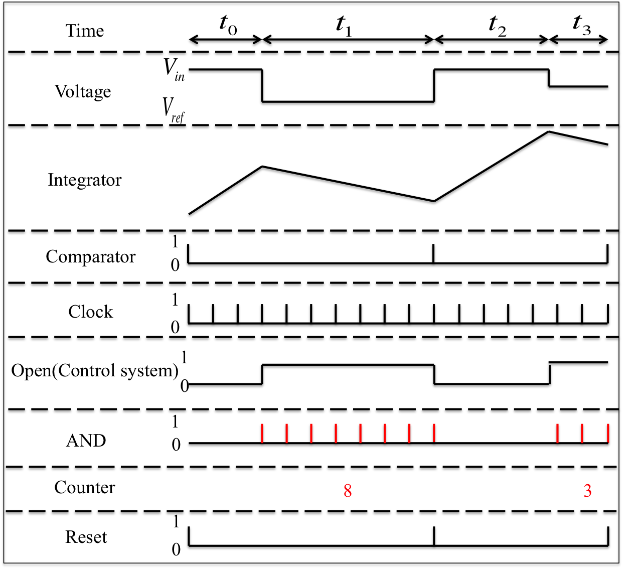
First, the switch on the input voltage (Vin) side of the analog input is turned on, and the resultant Vin is integrated for a set time t0. After t0 has elapsed, the Vin is switched to the reference voltage (Vref) side, and Vref is integrated by an integrator for a period of time t1. Then, the output gradient from the integrator becomes negative, and the output decreases. This occurs because Vref has opposite sign to the analog Vin.
Step 2:
The output from the integrator is compared with the ground (GND) value by the comparator, and if the output value corresponds to that of the GND, the comparator outputs “1”. Otherwise, “0” is outputted. The “1” output causes the integrator output to become “0”.
Step 3:
The control system activates the switch in Step 1, and gives the order to reset the counter and to open the AND gate.
Step 4:
When the AND gate opens, the counter begins counting the number of clock signals.
Step 5:
When the output value obtained by the comparator in Step 2 changes from “0” to “1”, the control system gives the order to close the AND gate, and the counter stops.
As mentioned above, the analog voltage is converted to a digital value based on the number of counted clock signals. The conversion rate of the double-integral A/D converter is relatively slow; however, this device is used for voltmeters outputting digital values, because it has high resolution and sensitivity.
In an integrator, an integrated circuit (IC) element called an operational amplifier is used, which amplifies an analog signal. As shown in Figure 1, an operational amplifier has two inputs: V+ (non-inverted input terminal) and V- (inverted input terminal). Further, it can determine the output voltage such that the difference in potential between the two input voltages becomes 0 V. Although subtraction processing is necessary in order to measure the potential difference between the two inputs, it is very difficult to design a subtraction process in a reaction scheme using DNA molecules. Therefore, at present, we are unable to realize a double-integral A/D converter using DNA molecules. Nonetheless, the possibility to design an integrator using DNA exists. This is therefore an opportunity to implement an A/D converter, because subtraction processing can be defined using the two’s complement operation, which is one of the advantages of digitization.

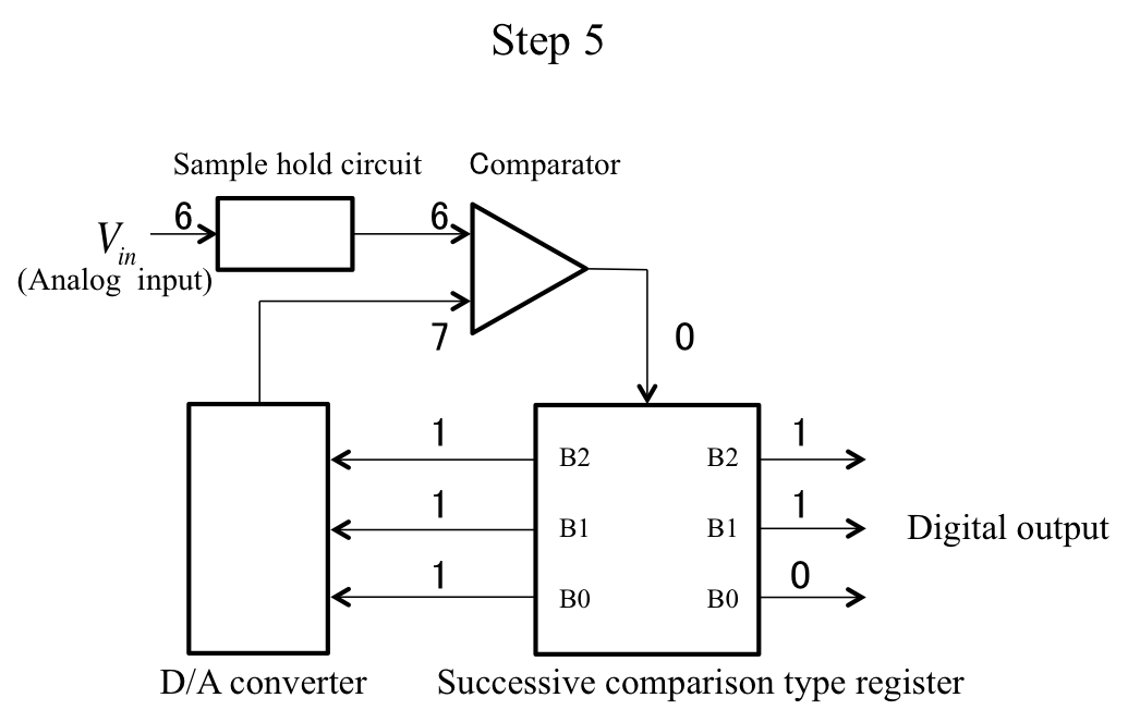
Successive comparison is a method that produces a digital output using a successive approximation to match an analog input voltage, on which a sample hold is performed, to a voltage outputted from a D/A converter. Figure 3 shows a successive-comparison-type A/D converter for a 3-bit output, showing the conversion of a 6-V analog input to a digital output value
Step 1:
The analog input maintains a voltage at a certain moment in time using a sample hold circuit. The successive-comparison-type A/D converter conducts more frequent signal voltage changes than the double-integral device. This function prevents the input voltage from changing while the sample hold circuit converts the analog input.
Step 2:
The comparator compares the output value of the analog input which is sample-held in Step 1 with that of the D/A converter output. If the former value is larger than or equal to the latter, the output becomes “1”. If the latter value is larger, the output becomes “0”.
Step 3:
The successive-comparison-type register functions as memory and stores the comparator output result in a high-order bit. First, this is stored only in B2, for which the most significant bit is “1”; that is, the D/A converter inputs 100(2) and the comparator input in Step 2 becomes 4 V.
As shown in Step 2, the comparator compares the 4 V output by the D/A converter with the analog input of 6 V, which requires conversion. Hence, because 6 V is larger than 4 V, B2 stores “1”.
Step 4:
From the result of Step 3, B2 stores “1” and the next bit, B1, becomes “1”; that is, the D/A converter inputs 100(2). This is why the input to the comparator becomes 6 V. When this value is compared to 6 V, as in Step 3, B1 stores “1” for equal analog input.
Step 5:
Finally, B2 = 1 and B1 = 1 are realized, and the least significant bit, B0, becomes “1”. Thus, the D/A converter inputs 111(2). As a result, the input to the comparator becomes 7 V. When this value is compared to the 6-V analog input, as in Step 3, the D/A converter output is found to be larger than 6V. Hence, B0 stores “0”.
In this way, the successive-comparison-type converter outputs a digital value using a bit-by-bit comparison, beginning with the most significant bit, against the sample-held analog signal. Although the successive-comparison-type A/D converter has a low conversion rate, it is possible to realize high cost efficiency, because the circuit is miniature and power consumption is, therefore, reduced.
A D/A converter is used in successive-comparison-type converters, as shown in Figure 3. Although the D/A converter exists only when the A/D converter is established, there is no such precedent that introduces digitization into DNA molecule circuits. If we adopt a successive-comparison-type A/D converter, we must design a new A/D converter using another method, and must also design a D/A converter.
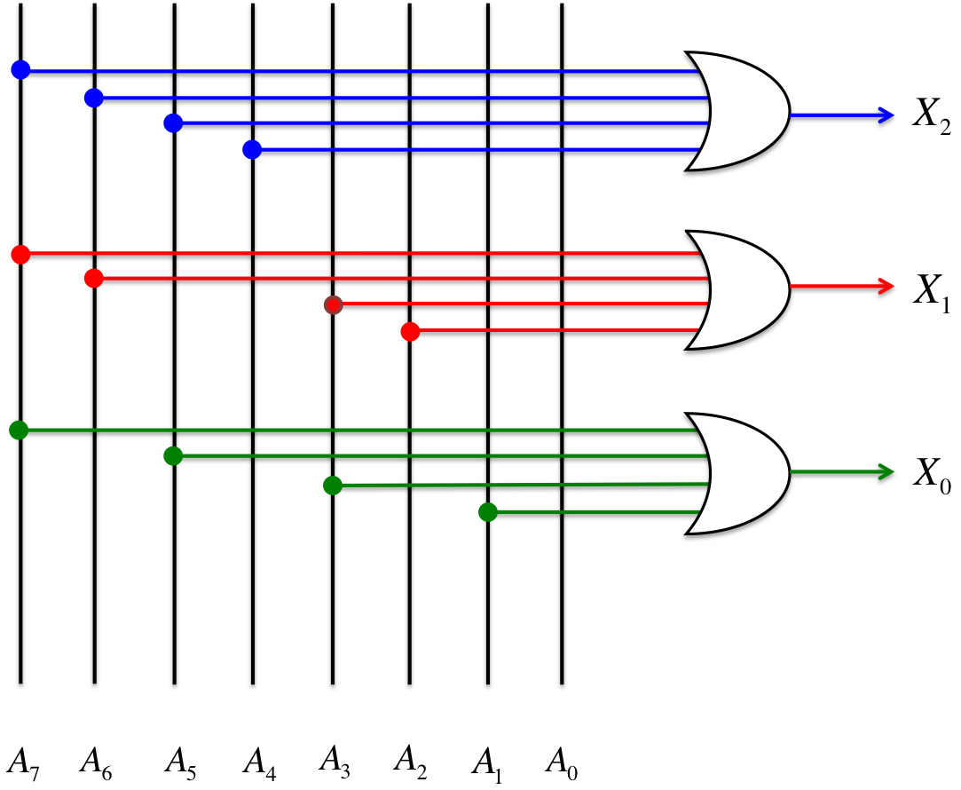
The parallel-comparison-type A/D converter is based on the characteristics of a parallel circuit. This converter digitizes an analog input at one instant by comparing Vref against Vin, which enters all comparators simultaneously. Figure 4 shows a 3-bit parallel-comparison-type A/D converter, which digitizes a 4-bit analog input. Additionally, Figure 5 shows the structure of an encoder.
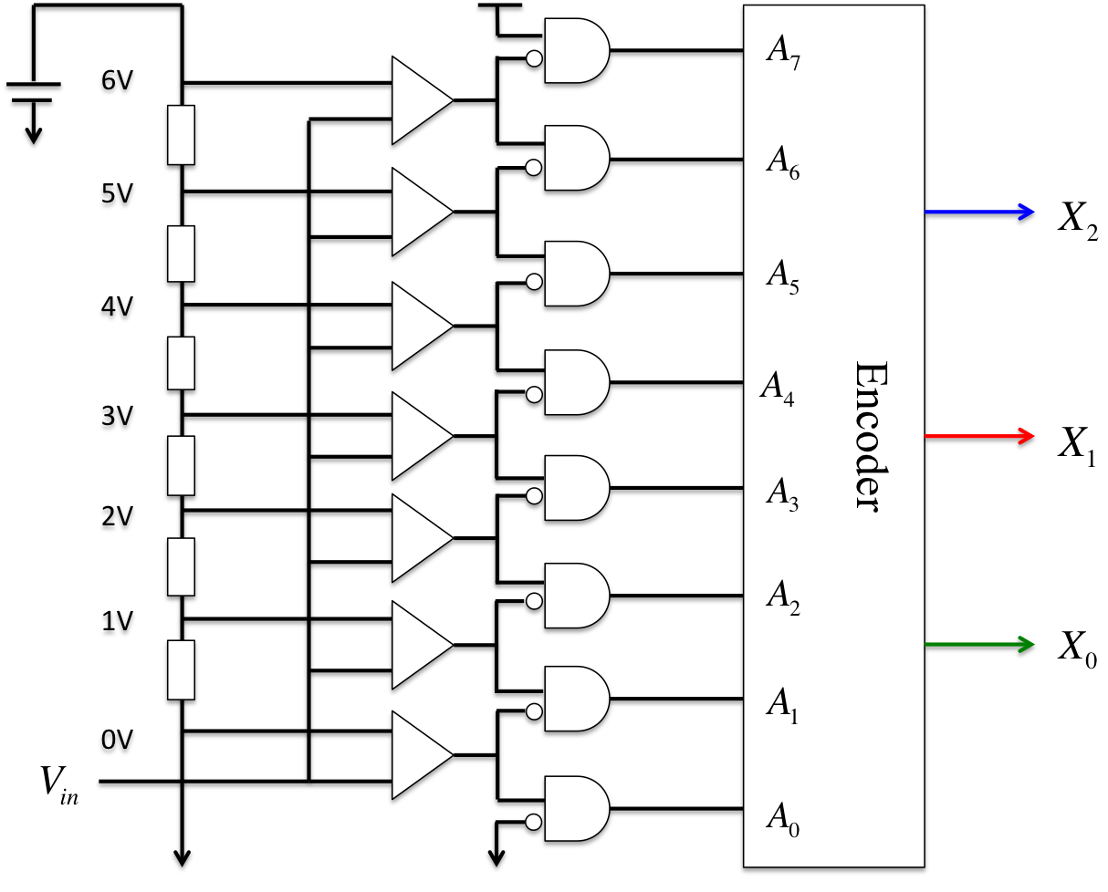
Step 1:
We assume that n is the number of bits, and the analog input Vin that we wish to digitize enters all 2(n-1) comparators simultaneously. In the case shown in Figure 4, we must prepare seven comparators for digital conversion, because the number of output bits is three (X2, X1, X0).
Step 2:
Each comparator discriminates between the values using a magnitude correlation, comparing the analog input Vin value against the Vref value. If the value of Vin is larger than that of Vref, the output becomes “1”. Otherwise “0” is obtained.
Step 3:
The A/D converter examines the “1”-“0” threshold obtained from Step 2 using a NOT and AND gate. We find that the threshold is A4, which is set to “1” in this instance, because Vin is 4 V.
Step 4:
The A/D converter converts data into binary digits on the basis of the data stored in the threshold gate obtained from Step 3, using the encoder, which consists of an OR circuit.
Parallel-comparison-type A/D converters tend to be large-scale circuits because the number of comparators must be increased significantly in accordance with increases in the number of bits, so as to improve the conversion accuracy. However, these converters are used to convert high-frequency analog signals such as video or pulse signals, which do not require precise digital conversion.
As shown in Figures 4 and 5, the parallel-comparison-type A/D converter consists of a simple circuit that is composed of logic circuits. It is difficult to increase the resolution without enlarging the scale of the circuit; however, this converter exhibits rapid conversion. Therefore, we conclude that the parallel-comparison-type A/D converter is suitable for replication by a reaction based on DNA molecules. We realize this parallel-comparison-type A/D converter using a combination of DNA logic circuits.
Digital etymology is derived from the Latin word "digitus" (finger), and means counting using fingers. Digital data are values represented by discrete values, whereas analog data consists of continuous quantities. We can imagine that digital etymology has good affinity with computing, as digital information may be represented by numbers such as “0” or “1”. However, analog quantities must be converted into strictly digital information for processing via computer, because analog data consists of vague values as a result of its continuous nature. We can understand analog data intuitively, however, digital data is suitable for computer processing for various reasons such as ease of information transmission. As a familiar comparison, records and cassette tapes are based on analog information, while digital information is used in compact disc (CD) technology.
2.1. Analog Information
Here, we consider a case where a sound is recorded as analog information that varies continuously. To use the above example, records and cassettes are based on technology that directly records sound waves. These sound waves are carved into the records and preserved in unchanged form.

Cassette tapes utilize a mechanism that stores the shape of the sound wave using magnetic tape.

We may assume that an analog system that simply records original sounds with 100% accuracy and then reproduces these sounds is superior to a digital system. However, analog systems have a significant weakness in the form of deterioration of information. In these systems, sounds are preserved on a recording medium such as a disk or magnetic tape; however, the quality of this recording medium changes over time. Therefore, digital technology is necessary.
2.2. Digital Information
What does it mean to convert analog data on a sound into digital data? Although a digital data-point can be expressed using a number such as “1”, “2”, or “3”, the sound data can be represented using just two numbers: “0” or “1”. Although we may think that two numerical values such as “0” and “1” can represent only two pieces of information, by increasing the number of digits to yield values such as “10110011”, it is possible to increase the range of data-points that can be represented.
2.3. Convert Analog to Digital
Representative examples of digital-technology-based music and video recordings are the sounds produced by digital audio players such as CD, DVD, and Blu-ray players, and iPods. Further, if digital information is recorded in "Yes or No" format, we can easily correct for missing sound data in the analog information. Music CDs have a mechanism through which sound is reproduced using numerical values, whereas records record sound in a waveform structure. For example, consider the following analog waveform.
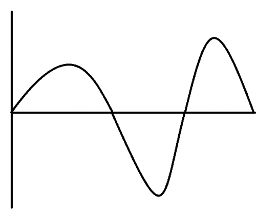
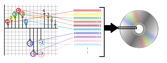
Firstly, the magnitudes of the sound’s amplitudes at constant time intervals are recorded as numbers in the digitization process (the vertical and horizontal axes are amplitude and time, respectively).
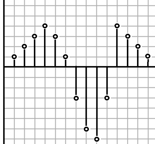
As regards recording frequency, the information is recorded at a frequency of 44,100 times per second in the case of a CD. Secondly, the amplitude magnitudes are quantified, as shown below.
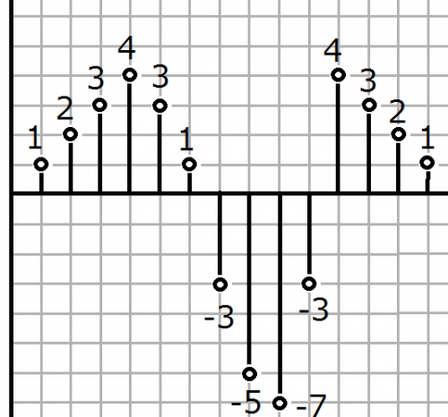
In the above figure, the information is digitized as "1, 2, 3, 4, 3, 1, -3, -5, -7, -3, 4, 3, 2, 1". An important aspect of the digitization process is that rounded-down values are recorded. In other words, a numerical value such as "12.3456" is recorded as "12.3". In the case of music CD, "16-bit" information is obtained; this indicates the number of quantization bits. Finally, numerical values are expressed in terms of two numerical values only, "0” or “1”, and the final results are recorded.